Meredith, Messerschmitt and the Whirlwind.
Meredith and Messerschmitt – more than just hot air.
Most historians of aviation are familiar with the Meredith effect, if only in relation to the P-51 radiator scoop. Dr Fred Meredith of the RAE has been described as working in theoretical numbers only when he wrote his 1935 paper “The Cooling of Aircraft Engines” Although it did describe in mathematical terms and with many equations how the heat energy from an aircraft radiator could be harnessed, there was also a paragraph in the paper which must have caught the eye of those working to optimise the new generation of 300 mph-plus aircraft. The wake from the cooling system may be used to augment the available energy of the boundary layer of the main airstream.
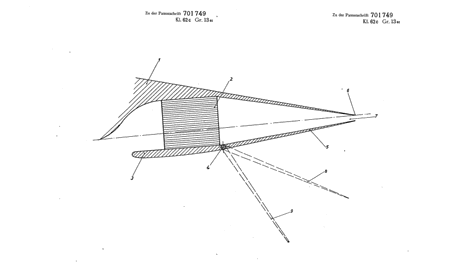 Messerschmitt's 1936 patent drawing
Not only would re-energising the boundary layer reduce drag, it would prevent separation, eliminate vortices and, with suitable manipulation, increase lift. Crucially, flaps with this kind of drag reduction could be usefully exploited for take-off. This certainly won’t have escaped Willy Messerschmitt, who was fully engaged at the time in literally and figuratively exploring the boundaries of aerodynamics in both high-lift and high-speed flight. Less than a year after Meredith’s paper, Messerschmitt filed a patent for a flap behind a radiator that would make a suitable Meredith jet nozzle when closed and an augmented high-lift device when open. He wrote "this is done in such a way that the spreading flap of the cooler, installed in the aircraft wing, is pivotably or rotatably hinged to the underside of the wing near the trailing edge of the cooler and extends to approximately the trailing edge of the wing. In high-speed flight mode, the flap position will be such that only a small slot is created, while in climb flight, a larger slot width is created by further deflection. The great advantage here is that the flow behind the deflected flap does not break down, and that the outgoing or blown-out cooling air ensures good airflow. This results in a very low drag coefficient with a high lift coefficient"
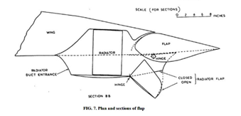
Bf110 radiator install, from a British intelligence report
What Messerschmitt actually did when designing the Bf110 heavy fighter was to make use of a design patented by Otto Lachmann and his team at Handley Page for a spreading flap, just as described by Messerschmitt in the patent’s text. Whilst not quite all the way to a Fowler flap, this flap was an aerofoil profiled to take full advantage of the Coanda effect, where energised airflows ‘stick’ to surfaces and curve around bodies of the right profile.
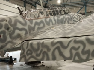
Outlets
One thing a researcher learns when it comes to ‘source material’ in aviation History is that originality doesn’t equal veracity. On April 1 1941 Vultee Aircraft received Messerschmitt 110D 0-B Wk. Nr. 3341 in Los Angeles. It had been shipped from the UK aboard the SS Montanan in April 1941, after being shot down near Croydon on August 15th, 1940. Nowhere was it recorded why a major intelligence asset went to the opposite shore of the US, to be given to a relatively minor manufacturer for disassembly and inspection.
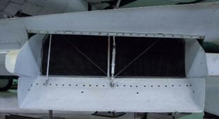
Me110 radiator outlet, with flap removed
An otherwise rivet-level description of the Bf 110 later published by Vultee does not mention the notch cut from the screen at the back of each of the 110’s wings to allow some of the air exiting the radiators to bleed upwards, providing the advantageous energising flow over the flap described by Messerschmitt’s patent.
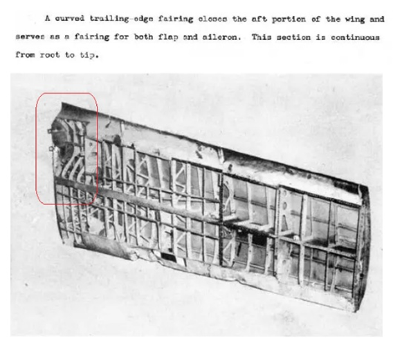
Photo from Vultee report
Indeed the report’s authors specifically stated the trailing edge fairing ahead of the flap was continuous, which it clearly isn't in accompanying photographs.
By 1941 it had been recognised that the current generation of domestic US fighters just wouldn’t cut it in a European conflict and many urgent consultations were taking place behind the scenes as US designers and engineers sought to absorb as much as possible from European manufacturers in a bid to produce a new generation of high-performance fighting aircraft. The P-51, for example, not only took advantage of the Meredith effect but also incorporated the work of no less a luminary than Beverley Shenstone in stripping away the boundary layer at the duct entry and making the radiator properly efficient.
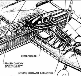
Vultee drawing of XP-54 showing airflow over flaps as arrows.
Vultee were engaging NACA in still partially-classified work designing the unconventional XP-54 ‘Swoose Goose’ pusher. Many accounts claim this was the first aircraft design with a ducted wing, where the cooling air entered at the leading edge, passed over the radiators, and then exited over trailing edge flaps. Of course, this ignores the Whirlwind. It seems more than coincidental that the one feature of the 110 not mentioned in the report shared with the industry by Vultee became an innovative feature of their own proposed design.
Borrowed engineers
On August 3, 1941, four months after Vultee first received the 110, the New York times reported “To rush new designs to completion, Northrop Aircraft, Inc., of Hawthorne, Calif., last week “borrowed" eight research engineers from Vultee Aircraft, Inc. They will immediately start work in the research department”. The research department at Northrop were already engaged in meeting a USAAF a request for proposals for a high-altitude bomber that could carry a 10,000-pound bombload halfway across a 10,000-mile range.
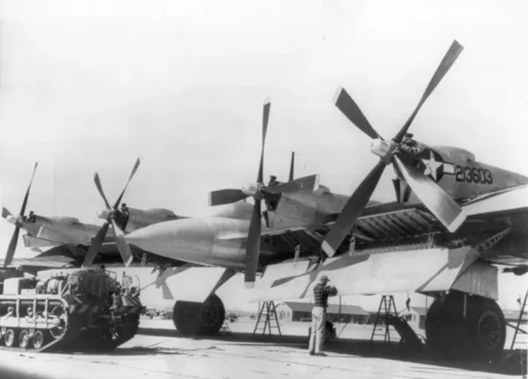
YB-35
It is impossible to be certain of the reasons for their engagement, but the coincidence in the appearance of trailing-edge radiator outlets over flaps on the YB-35 is interesting.
Joining it up
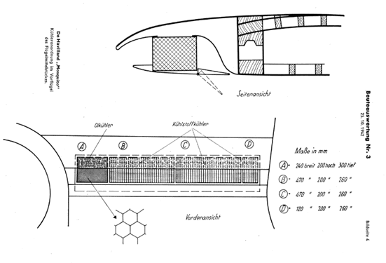 Mosquito radiator installation, from a German intelligence report
The DH Mosquito famously used a leading-edge radiator, while in the US NACA claimed to have perfected an intake shape that removed all boundary layer effects and maximised flow by 1940. The major barrier – quite literally – to continuous flow through wing mounted radiator systems was the wing structure itself.
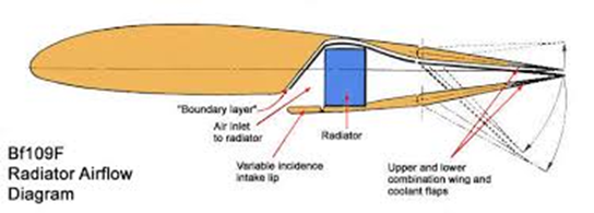
Messerschmitt Bf109f Radiator installation, with trailing edge exit
Universally, wings had spars. This meant that whilst several successful allied designs had wing intakes, and several successful axis aircraft used ducted efflux at the trailing edge, it would take a spar design with openings large enough to pass the enormous volumes of air needed by liquid cooling systems before an end-to-end direct passage was possible.
It fell to a small manufacturer of farm machinery in Somerset to put it all together in an effective package.
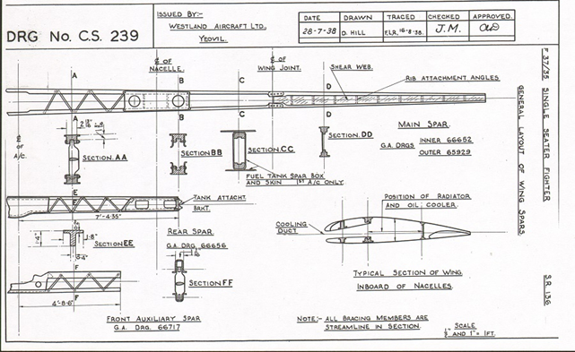 Whirlwind lattice spars
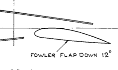
The Westland design team of H. Widgery and W. H. Paine, under the newly-appointed W.E.W. Petter, came up with a design that included not just one but three spars that, where they intersected with the airflow, made use of diagonal streamlined braces in place of a web, making a continuous chamber between inlet and outlet. With the addition of a Fowler Flap, the whole system was designed to perform three different functions - net drag reduction when ‘closed’, maximum cooling action when fully open, and lifting flap action with attached boundary layer when partially open
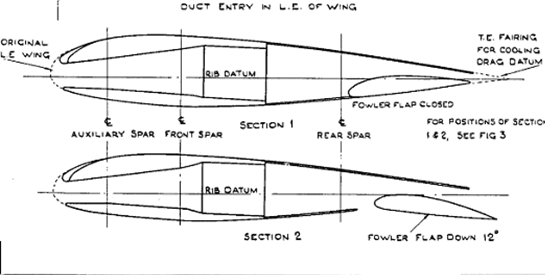
Whirlwind radiator, spar and flap positions
That a ‘blowing’ effect over the flap was in the mind of the design team is suggested by the careers of the Westland team. W H Paine went on to conduct the only British study of blown flaps in the 1950’s whilst still working for Westland Aircraft - work that led to the Hunting H.126 blown-flap research aircraft. Meanwhile, Widgery’s previous position before joining Westland was head of wind tunnels at Handley-Page – where the spreading flap used by Messerschmidt was developed. 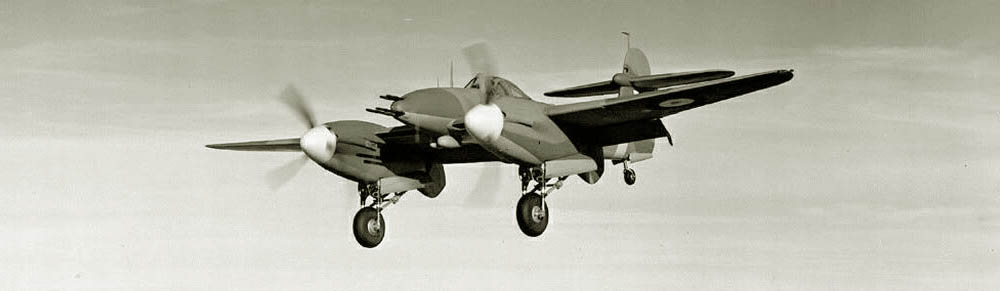
Both the Whirlwind and the 110 had a tendency to float tail-high on landing unless the stick was held firmly back. This may have been due to the Coanda effect of attached flow over full flap.
Also on the design team was aerodynamicist John Carver Meadowes Frost. Frost went on to design the worlds only viable flying saucer, the Avrocar, which relied solely on the Coanda effect for lift.
This is not to say that the translation of theory into practice was perfect. Whilst the divergent duct ahead of the radiator lowered the air velocity, increased cooling and reduced drag, aft of the radiator there is no duct as such, instead just the wing’s convergent interior complete with ribs, spar braces and stringers. Whilst flow was smoothed again by the flap surface and upper cooling door, having full ducting behind the radiators would probably have made made this far more efficient.
To further confound what was otherwise a superb engineering solution, and in inimitable style, Petter went on to overcomplicate the system. The idea was that in the partial flap, high-lift configuration an extra cooling flap would deploy automatically via a cam linked to the flap., as this was when the greatest demand for cooling would occur, during the climb.
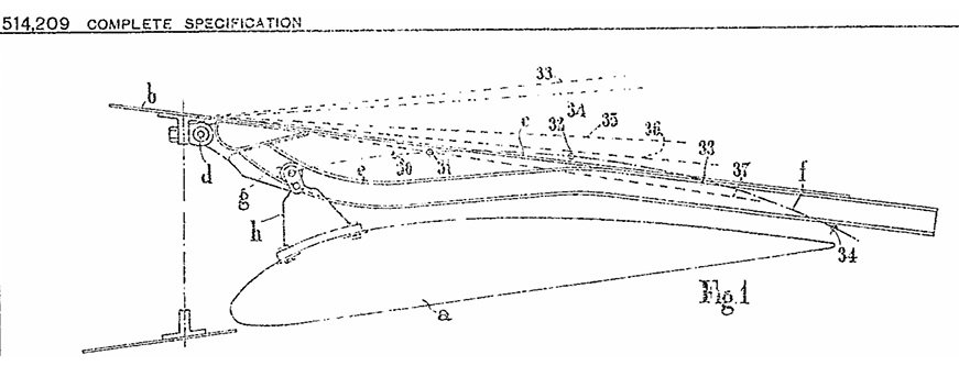
Westland 1938 patent application
Although a neat idea in theory, in practice this meant the pilot had no control over engine cooling that didn’t involve changing the flap position, leading to overheats and performance limitations.
Close Relations
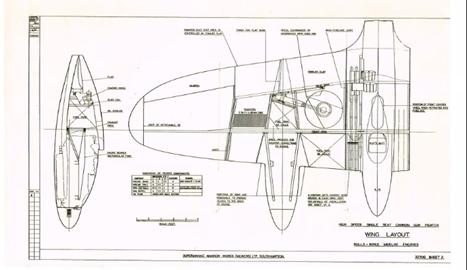 F18/37
A very close relation of the Whirlwind’s duct appeared in Supermarine’s 1938 designs for Air Ministry specification F18/37, the types 324 and 325 heavy fighters. One GA drawing of a development of these, 32700 Sheet A, explicitly states “Radiator duct exit area is controlled by Fowler Flap”, whilst showing a smooth-walled chamber.
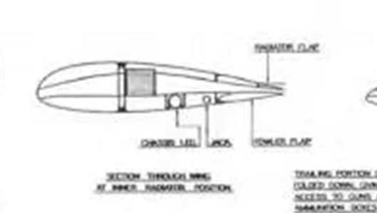
Although these designs were never built, Supermarine did of course produce the Spiteful as a Spitfire replacement, and this sported a landing flap that doubled as an outlet flap. Often cited as a laminar-flow design, the section inboard was more of an NPL high-speed profile, lending itself to a radiator installation further aft in the wing. Rowing back from the 327's leading edge ducts and fowler flaps, the design owed much more to Messerschmitt's original patent drawing.
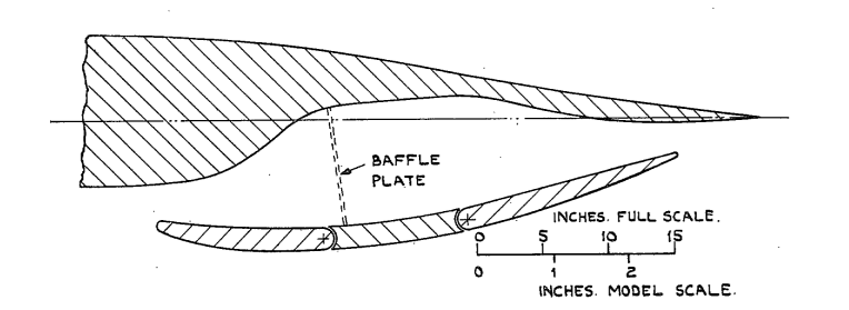 Wind Tunnel model diagram of Spiteful duct
A split flap was also the option chosen for Westland’s Welkin, their next production design, with refinements to the duct exit applied to the Mk. II – although details are scarce and sources contradictory, Welkin technical data being even rarer than that for the Whirlwind.
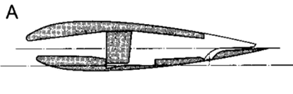 Welkin duct
Hot again
For a long time since the 1940’s, boundary layer control has been coming in and out of fashion. The advent of jet propulsion removed any hint of radiator input but both compressor air and exhaust bleed have frequently been applied to flaps, though always via narrowly directed jets (internal blowing). More recently, turboprops have blown propeller stream more generally over flaps (‘external blowing).
An increasing focus on high-lift, high-efficiency systems in the past two decades has produced many re-inventions of this particular wheel, visible in patents applied for around the globe for high-lift and drag-reduction flap systems. However, one in particular stands out for its familiarity.
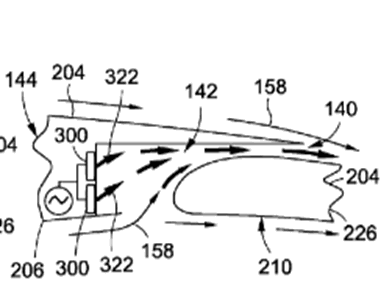 Boeing patent
A 2018 Boeing Patent describes how “the air jet is discharged into the main cove and mixes with ambient flow flowing upwardly into the main cove from a lowermost surface of the airfoil at an entrainment point located aft of the ejection port before passing out of the main cove and into ambient flow passing over an upper surface of the trailing edge device. All of that was summarised by the image above.
This design draws together the movable fowler flap and the associated cavity opening underneath the ‘main cove’ as Boeing put it, and the use of an internal energised airflow, mixing it with the ‘ambient flow’.
 And so, while the application was imperfect and flawed by ambition, Petter’s team would appear to have been decades ahead of the game. Whilst some appreciate how advanced the state-sponsored technocrats in Germany became in theory and practice, and others quite rightly give plaudits to the immense efforts of the engineers employed privately and publicly in the US, the achievements of the team from a small town in Somerset remain almost entirely unrecognised.