Well, try this then: Hawker Fury K1928 – Cambridge Bomber and Fighter Society (cbfs.org.uk). I hope to go and visit them soon to examine the Hurricane undercarriage.
Steve Smith
What is the difference between the (5" bore) supercharged variants of the Kestrel and the Peregrine?
Steve Smith
What is the difference between the (5" bore) supercharged variants of the Kestrel and the Peregrine?
Hi, the original concept of the Peregrine engine was to be a high horse power development of the Kestrel engine. The new design called for a wider separation of the bore centre lines with a wider vee angle for the cylinder blocks. The redesign never took place, in reality the Peregrine was a over grown Kestrel. While there were many differences to the internal components, rods, cams, pistons etc the basic design was the same. this was the main reason for the engines overheating problems. In short a 25% increase in power output contained in the same capacity water jacket. While greater capacity radiators were utilised in the Whirlwind, the internal wing mounting position exacerbated the problem. The water pump and water outlet position were the same as the Kestrel, which had like the early Merlin's been designed for underslung radiators. This resulted in no natural thermo-syphon effect in the Whirlwinds cooling system. The problem was never corrected, only overcome by using 100% glycol as against the normal 30% glycol water medium.
This is fascinating and opens up the engine provision discussion somewhat. I'd thought that the acquisition of an actual Peregrine was a dead end apart from finding a pair in the ground or making engines. Now it seems that if we could somehow assemble the latest (but not assumed) Kestrel, a visitor would not necessarily distinguish it from a Peregrine.
In fact you can buy a Kestrel or parts for them, given the funds...well, at least we know where we are. I've started to pick up all sorts of info on the Kestrel such as the Gilman Bearings and the 'composite' cooling. There is documentation, including engineering information, from places such as the Old Warden Shuttlesworth archives and doubtless other places as well.
What do we have already on the kestrel so that I wouldn't duplicate the work?
Steve
ps below is info on the Gilman Bearings-the patent via Key.Aero
Gilman Bearings
Method of Making Bearings US patent 2130461
In the development of motors designed for high. speed and heavy loads it is important that they be of the lightest weight possible in order that the least amount of power may be required to propel their own weight and, therefore, that metal of the lightest weight possible be employed.
This has resulted in the improvement of metals used for such purposes so that the weight has been decreased without impairing the strength and endurance qualities but more flexibility has resulted, such improved metals being capable of withstanding more or less flexing. Such flexing of the metals as well as the speed of or the load carried by the motor causes a strain upon the bearings used which breaks down lining of such material as Babbitt metal, which has heretofore been generally employed for such purposes, and also results in.the loosening of the bond between the Babbitt lining and the metal of which the shell is composed, thereby materially decreasing the life of the bearing and impairing its efficiency in use. Inasmuch as the value of the motor in service can equal only the life of the bearing it becomes more and more important in the development of this art that bearings be provided which will stand up under the flexing and the great speed and the great load imposed without danger of destruction in the performance of such duty and particularly without separation of the metals of which the shell and the lining are composed.
The object of my said invention is to provide a bearing and a method of making the same composed of metals which will provide a bearing of the necessary strength and rigidity and a bearing surface which will be of comparatively soft wearing quality but at the same time capable of resisting much higher temperature and withstanding much greater strain or "pounding" in service than metals such as Babbitt metal; and also one in which the metals are united by a bond that makes them practically integral and incapable of separation under flexing or any other strain. I have found by experience that a steel shell affords the best foundation for a bearing such as, required for the purpose indicated for the reason that it may be of lighter weight for the same degree of strength than any other metal which I have found suitable for the purpose. I have also found that so-called "plastic bronze" makes a most desirable metal for the lining or wearing surface for the bearing. By "plastic bronze" I mean a composition composed of copper and lead the proportions of which may be varied to suit different conditions and different requirements, a suitable composition being thirty (30) parts of lead and seventy (70) parts of copper. "Plastic bronze" is generally understood to also include, if desired, copper alloys of from 4% to 7% tin with 20% to 30% lead and with or without small quantities, of nickel. It will be understood that in using the term "plastic bronze" herein it is intended to include all such suitable compositions and variations thereof. As is well known the melting point of steel is considerably higher than the melting point of the bronze but the melting point of bronze is very much higher than the melting point of babbitt and the bronze of a composition such as above indicated while affording a most excellent surface for the bearings of high speed motors, nevertheless is of a density and tenacity capable of resisting the wear and heavy duty required.
In the manufacture of bearings of my said invention I employ a method by which the steel shell and the bronze lining or bearing surface are united by fusing the two metals to unite them by a bond that makes them practically integral and permanent so that separation under any strain, load or flexing imposed by the duty of the motor is impossible.
In the accompanying drawing, Figure 1 illustrates a bearing such as contemplated by my invention, the bearing housing usually of aluminum or any other appropriate metal being indicated by the reference letter A, the steel shell by the reference letter B, and the bronze lining by the reference letter C.
In Figure 2 I illustrate a method of forming the bearing which consists in mounting a cylinder D with a bottom d within the shell B and pouring the molten bronze from a ladle E into the space between the cylinder and the inner surface of the shell. It will be understood of course that the ends of the bearing are machined off appropriately after the bearing is finished. The bottom d of the cylinder D is large enough to cover the end of the shell B as clearly indicated.
While I have illustrated this as a method by which the molten bronze may be applied to the shell it will be understood, of course, that any other appropriate method may be employed, whether it be the method of pouring, the method of die casting, or the method of applying by centrifugal force or any other method now known or found appropriate. And I also want it understood that while I have specified "steel" and "plastic bronze" as the two metals preferable in use that these terms are used as meaning any of metals that may be found capable of the use intended. Further, while the method described has been found particularly adapted for the purpose set forth it will be understood of course that it may be modified within the scope of the appended claims. For example, the steel shell and lining metal may be heated together to a temperature where the lining metal will be a substantial degree above its melting point and the steel shell a substantial degree below its melting point or the parts may be heated separately to different temperatures so long as the steel shell is a substantial degree below its melting point and the lining metal a substantial degree above its melting point. The two metals may be united or applied to each other in any manner found practicable, the particular method illustrated and described being one that I have found suitable for the purpose. As will be understood the steel back and the lining metal may be united in flat sheet form if desired and then rolled or otherwise shaped to form a bearing of the shape desired.
In the practice of the method by which these bearings are produced the steel shell of appropriate thickness is heated to a temperature which is approximately the temperature required for melting the bronze metal which is to be used to provide the bearing surface. The bronze metal is heated not only to the melting point but to approximately two hundred (200) degrees above its melting point and then is applied to the surface of the shell by the method heretofore described and illustrated in Figure 2 of the drawing or by any other method found appropriate.
The bronze metal being in a fluid condition and the steel of a temperature substantially the same as that of such bronze metal the two metals fuse and unite firmly together forming a bond that makes the two metals practically integral and incapable of separation regardless of strain, flexing or other duty imposed in use.
After the bronze metal is poured or otherwise applied to the steel shell it is allowed to cool for a short period sufficient to allow the two metals to fuse together but before the lead in the composition of the bronze can settle and separate from the copper by reason of its greater gravity the bearing is immersed in a cold bath and cooled quickly so that the copper and lead content of the bronze composition are held in the metal properly mixed and of the same relative proportions throughout.
The bearing resulting from the practice of the method herein set forth is made the subject matter of another application No. 575,117, filed November 14, 1931, as a division of this application.
While I have illustrated a bearing with the shell lined on its inner surface with the bronze it will be understood of course that its outside may be in a like manner covered with a bronze bearing surface or the bearing surface may be applied to both sides of the steel shell, depending upon the character of use for which the bearing is intended.
By this method a bearing is provided which has been found capable of withstanding the severe requirements of motors designed for the highest speed in airplane and other service and by actual test and comparison such bearings have been able to far exceed in their efficiency in these respects any bearings made by any other processes heretofore known.
Having thus fully described my said invention, what I claim as new and desire to secure by Letters Patent, is: 1. The method of forming bearings which consists in heating a steel shell to approximately the melting point of the bronze lining metal, heating the bronze lining metal to a temperature higher than its melting point, depositing said lining metal while so heated upon the surface of the heated shell, permitting the two metals to fuse and then rapidly cooling the same.
2. The method of forming bearings which consists in providing a steel shell of relatively light, flexible character, heating said shell to approximately the melting point of a plastic bronze lining metal, heating said plastic bronze lining metal to a temperature higher than its melting point, depositing said lining metal while in its molten state upon the surface of the heated steel shell, pausing for a short space of time to permit the two metals to fuse and then rapidly cooling the same.
3. The method of forming bearings which consists of heating a steel body to a temperature higher than the melting point of a composition metal for the bearing surface, mounting a cylindrical core concentrically within said heated steel body, then applying the composition lining metal heated to a temperature higher than its melting point in the space between said core and steel body, allowing time for the two metals to fuse. and then immersing the bearing and core in a cold bath to set the composition.
4. The method of forming bearings which consists in combining a steel shell of relatively flexible character with a lining, of "plastic bronze" by heating the two metals to a temperature that will not melt the steel but will melt the lining metal, permitting the two metals to fuse and then rapidly cooling the same.
5. The method of forming bearings which consists in combining a steel shell with a lining of "plastic bronze" by heating the two metals to a temperature that will not melt the steel, but will melt the lining metal, permitting the two metals to fuse and then rapidly cooling the same.
6. The process of producing a bearing having an outer iron or steel layer, and an inner layer consisting primarily of copper and lead, said two layers being autogenously welded together at their meeting surfaces, which process comprises contacting a molten mass of said copper and lead to form said inner layer, with said outer iron or steel layer heated to a temperature sufficiently high to produce an autogenous weld between the layers; permitting said bearing to stand for a time sufficient for an autogenous weld to form between the layers; and finally drastically chilling said bearing.
NORMAN H. GILMAN.
I have more questions. Do we know whether the revised drawings for the cooler Peregrine are still available from RR. I'm thinking of the Rolls Royce museum if it is still there. I went there once before to photograph.
Others later.
Steve
Others later.
Steve
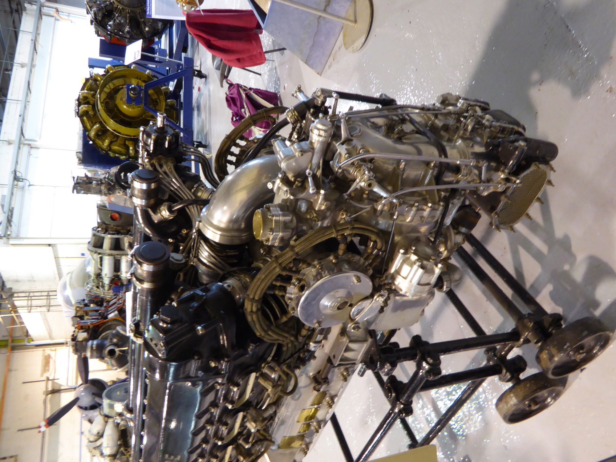
Hi, relating to the questions. I believe the RR museum is now closed, at least to the public. not sure if their archive material is still accessible. We have the two Steve Visard owned damaged Peregrines from the museum down at the battle of Britain museum, they are beyond restoration, but provide a full reference. Not clear on what you mean by the cooler Peregrine. If you mean the proposed Morris film type radiators against the as fitted air flow radiators, then yes I have the original works drawings for their instillation. If you mean the later redesigned Peregrine, then no, the redesigned engine which formed the basis of the Vulture X engine 24 cylinder. The redesign was actually the original design for the Peregrine, but now mounted to an X configured crankcase. I have never found or seen any archived information that a V12 was ever produced. The Vulture which powered the Manchester bomber was a successful engine, which highlights the original design concept for the Whirlwind would also have proved to be a success. The later developed Kestrel engine produced over a 1000Hp on the 100 hour test, but I have no information as to whether it ever went into full production. There is anecdotal information that the engine was adapted for marine use, to power the Higgins class of landing craft, not sure of the veracity of this information, my understanding being that the Higgins craft used a Packard marine V12 ( not a converted Merlin)
By 'cooler' Peregrine I was meaning the 'new design called for a wider separation of the bore centre lines with a wider vee angle for the cylinder blocks'. Anyway, it focuses us on a) what drawings/blueprints we have and more importantly, what we still need. b) what our general course is. By this I mean: 1) existing capability for mould making for a Kestrel/Peregrine cylinder block for example. How to make such an assembly of moulds that could result in a casting that was accessible for finishing machining (internally as well as out). I am a member of SMEE so there might be some machining possibilities there and also someone who has made a pre-war half-size aero engine. 2. Whether we would want to pursue a further development of the Peregrine re different block and cooling (very interesting but would entail half-size testing), or whether we're aiming to produce two exactly as they were during the war (I suspect the latter is the case). 3. I'm also wondering whether we should have an 'engine' committee (unless we've already got one?) to work out how to fund this in the same manner as other 'difficult' things are attempted in the preserved railway sector for example). Anyway, we could do more than contemplation I would hope. The material in the previous reply is very interesting and thank you.
Steve


Yes, the two Peregrines in the museum are shown above and one is much better than the other. I have many other detail pics of these if they would be useful in the future but I believe you have them all. They were taken at the RR museum when it was open.
Steve
Steve
Yes, the two Peregrines in the museum are shown above and one is much better than the other. I have many other detail pics of these if they would be useful in the future but I believe you have them all. They were taken at the RR museum when it was open.
Steve
Hi, Steve. While I would love the possibility of producing engines, the undertaking of such would be a venture into Pandora's box territory. The redesigned engine (the concept engine) was a very different beast from the Peregrine. Wider separation of the bores required a total redesigned of nearly every component, crank, cams, cylinder heads etc. The early Vulture engine also had its problems resulting in a redesign of the con rods to a four bolt configuration, there was still an overheating issue requiring a new design of water pump impellor and fitting three oil pumps. I don't know if RR have any drawings etc or even if they would release them. In any event to undertake such a task would run into many hundreds of thousands of pounds. An American company produces a modern V12 aero engine in the horse power range of the Whirlwind and they were in excess of £250K a piece. If we were to pursue the engine route I would be thinking more along the lines of Kestrel engines, or even Meteor engines,( non supercharged Merlin's) without the super charger casting they would fit in the existing nacelle lines of the Whirlwind. Either way there would still be a significant cost element. Remanufacturing a Peregrine would also require a major financial commitment. While producing castings etc is feasible (Retro track and Air) are producing Merin castings, don't think the do crank cases yet but it was on the cards. The main block would be the forgings for the crankshaft and con rods, the dies alone would be very very expensive. Thoughts welcome
Say Hello to Paul at Little Gransden for me. Can you have a look at the wings - have they started on the longitudinal formers yet? The new drawings for the insides of the original fabric wings were done by yours truly - the trickiest geometry in the world, making a tapering warren truss with an aerofoil section!
OK, maybe the second trickiest, after Petter's logic-defying Whirlwind Cockpit.
Re the engines. to get ones that turn over would just be horribly expensive, but a good metal replica - well, that would be great! Ideally, something that's peregrine on the outside and ford three-cylinder on the inside would be the cheapest way to get props turning - but I'm not sure what use that would be to the 'keepers'. Dave, any thoughts?
..and to add, we might even be able to mount one of the two survivors in our aircraft to illustrate a Peregrine with the cowl off in the meantime, as a display idea.
Yes, I hope to meet Paul at the airfield workshop. I think this thread should continue into details about what we seem to need, which is a couple of Kestrel cranks, bigger castings and so on, in a retrievable condition. I'd prefer running engines; they don't need to be tuned right up or otherwise stressed. A fallback would be one in working order and another intact and fitted. Which organisations/museums/ preservation groups have dealings with Kestrels? Need a list.
But alongside the idea of a temporarily fitted recovered Vizard engine we do, I hope, have collaboration with our hosts for publication and regulatory purposes. And, we have to look at fundraising square in the face. So with that in mind, I'm proposing that we use another thread specifically for just that. Here goes:
But alongside the idea of a temporarily fitted recovered Vizard engine we do, I hope, have collaboration with our hosts for publication and regulatory purposes. And, we have to look at fundraising square in the face. So with that in mind, I'm proposing that we use another thread specifically for just that. Here goes:
https://www.aerovintagespares.com/shop/engines/engines-for-sale/rolls-royce-meteor-centurion-tank-engine/
Two Meteor Merlins would allow the completed Whirlwind to be taxied at Duxford? Financially it is more achievable.
Seems to me the Project would be best to concentrate on completion of the airframe before worrying about engines, especially as the BoB museum has two crashed examples of Peregrines that would be co - exhibited, The manufacture of engines is well beyond the capability of any enthusiasts group, and it is worth remembering when they were built by the probably leading UK , government funded, engine builder of the time, they could not in the end allocate sufficient resources to fully support development and manufacture
I don't think anyone would dispute that the airframe is of the utmost priority for time and funding at present but the engines may need thought and planning if major funding is necessary. Therefore unless any of us are experts in obtaining money, including me, we have to learn how to do it. For example I used to be terrified by lectures at conferences when I was young but giving presentations about the Whirlwind might be one way of tackling it. I will start the Whirlwind painting when I've got my Land Rover engine back together and the grandchildren have gone back home. Then it'll be back to getting a '63 London cab back on the road and two differentials. Model engineering has gone out of the window at the moment and so has my writing, but a friend bought a book the other day...so a single person might even review it.
Steve
Steve
Not personally into putting Meteor Tank Merlins into our bird ever. They would require completely different mountings and the form factor is wrong, even if they could be squeezed in (I am dubious about that - a larger block into a cowl that was notoriously close to the Peregrine block)?
Apart from the Rolls Royce badge there is no authenticity in doing this - its like trying to squeeze a Fordson Tractor engine into a Ford GT because it's a 4 cylinder Ford.
I agree that as a team we should focus on the build. We are able to fundraise and are doing so, and that cash is going on a clear sequence of events that we put before our benefactors and members.
It would be great to get late Kestrels in there pretending to be Peregrines. You would have to redesign downdraft supercharger inlets for them, and the challenge is not trivial. I would suggest a separate parallel project which you can lead on to gather the info, expertise, tooling and funds to do this, linked and mutually supporting.
OK. I'll start asking around. Sounds very interesting indeed.
Please could I have some engineering drawings of the Peregrine and relevant areas like supercharger & cowling, when you have time. I have Windows 11 here, Pshop, office, acrobat and Literoom, etc but no engineering software. I've ordered a book on the Peregrine and Buzzard but it may turn out to be little more than servicing/ pilots' notes. Thanks.
Best,
Steve
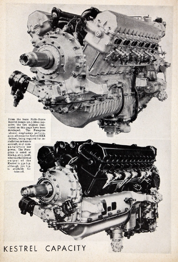
Peregrine (top)
Kestrel XXX (bottom)
So yes, - slightly different 'sump' to the crankcase and slightly different rocker covers, but the same block - except at the back, you can't see it particularly clearly in this front view but the Kestrel XXX has an updraft feed to the supercharger and the Peregrine a downdraft.
Nothing else but the latter will really 'work' in there apart from no supercharger at all. The downdraft arrangement is fundamental to the design of the aircraft, making room for the undercarriage. Easy to build a 'dummy' based on a knackered Kestrel or even a new block. Much harder to build a safe running example.
To address your previous, we don't have technical drawings for the Peregrine - we were never intending to build one!
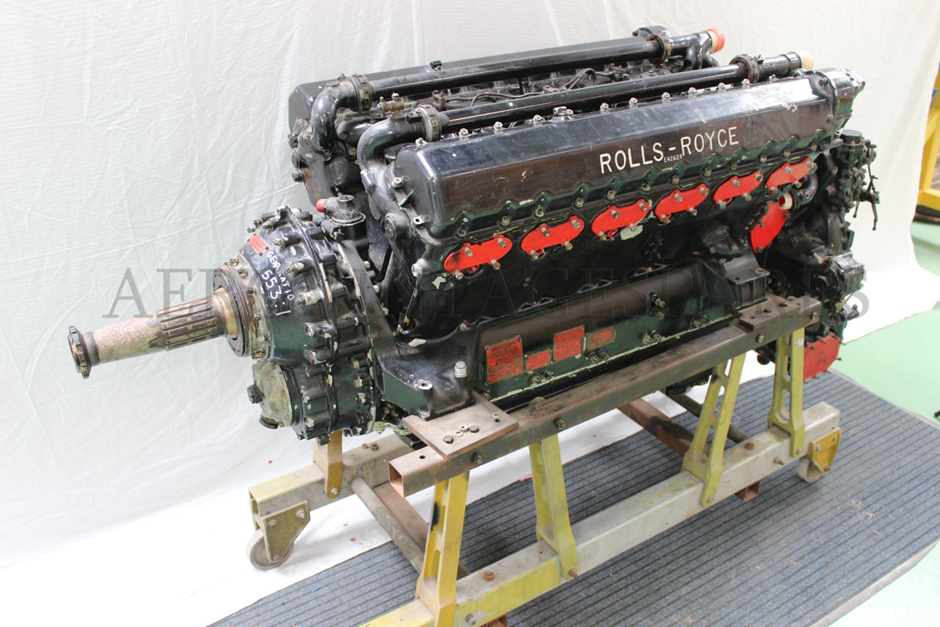
Thanks for that. I've been trying to find good comparative pics of the rear end. Next pic is a good resolution of a sectioned Kestrel.

Below: Peregrine


Kestrel below
Below: Peregrine
Kestrel below
Kestrel

Actually, I don't suppose the u/c will need folding.


Front end of rear part of nacelles.
Could do with some scale drwngs.
Steve

Looks like there is about 14" between the main gear frame and the front of the tyre in the folded position in Westland Drwng 255.
Am waiting for replies from Rolls Royce, Royal Aircraft Museum and Hawkinge re drawings and Kestrel parts, etc. If no go, will try the telephone. When have vehicle, will go to the Fighter & Bomber museum, Cambridge. Learning application of anaerobic sealants on ladder/crankcase joint. Been told, tiny roller may be better than bead.
Steve
Steve
Thought the UC will not need folding, we are building this as accurately as possible so the wheel wells need to be right. No intakes or ducting there, please!
As for drawings of the area, I don't know that they exist. Best (if not easiest) thing would surely be to use the dims from the Engine GA's to create a facsimile of the supercharger that is guaranteed to work with the design, whether running or not, rather than trying to create or adapt something different that 'should' fit?
As for drawings of the area, I don't know that they exist. Best (if not easiest) thing would surely be to use the dims from the Engine GA's to create a facsimile of the supercharger that is guaranteed to work with the design, whether running or not, rather than trying to create or adapt something different that 'should' fit?
Whot, no power take off from one engine, right through the wings via the cockpit to a dead one on the other side?
Dead right. I'd like to get my hands and a tape measure on a Kestrel and a barrow load of supercharger bits though!
I worked out dimensions before in another life; I had an entire set of clinical trial traces to interpret (in mV). I put them into some graphics software where I could measure distances.I just needed two definite reference distances and everything else followed. In the old days you'd have calibrated a chart recorder yourself and would know all the distances.
Steve
I'm allowed to put an article on the Whirlwind in the Society of Model and Experimental Engineers to increase awareness and in the hope that someone will admit to having Kestrel/Peregrine parts/drawings.
A suggestion from this group was to make the engine castings out of wood and spray them to appear as metal with grease marks, etc and then add metal fittings. This method has been used elsewhere where engines aren't available.
I'll proceed with the article.
Steve
A suggestion from this group was to make the engine castings out of wood and spray them to appear as metal with grease marks, etc and then add metal fittings. This method has been used elsewhere where engines aren't available.
I'll proceed with the article.
Steve
Thanks Steve. We have had a similar conversation and the upshot is that we make the airframe complete with the correct bearers, and if it comes to it mocked up engines will be made to fit. These will need to hold the props on, of course, so some internal bracing will be necessary.
Of course, if you or the group could produce a couple of Peregrines that would be better..
Of course, if you or the group could produce a couple of Peregrines that would be better..
Agreed. Real engines would be much better. Proceeding on that basis.
Regards,
Steve
Regards,
Steve
Tried Neil Chattle at Rolls-Royce today but they can't help us at the moment because they have their own problems. I won't repeat them here. The willingness to supply drawings at some point in the future or Kestrel help will depend on their re-organisation and whether the aircraft is static (safety).
In the words of the Enormous Crocodile. "I have other nasty and terrible plans", B, C and D.
In the words of the Enormous Crocodile. "I have other nasty and terrible plans", B, C and D.

 Kestrel
This (the X), is an unsupercharged version of the Kestrel: so avoiding the supercharger input relocation but being less like a Peregrine. the IV in the drawing is supercharged?
Steve
Steve